EN
EN
- Overview
- Specification
- Appearance
- Related Products
- Utilizing advanced power electronics technology, the system features stepless voltage regulation with high precision, ensuring a smooth adjustment process without interruptions.
- The power section of the converter employs an LCL filter, providing effective filtering that eliminates high-frequency harmonics from the output. This design ensures that there is no interference with other systems and equipment.
- The compensation voltage can be adjusted according to user requirements, with configurable regulation speed and independent phase control to accommodate severely unbalanced loads.
- The converter is designed with a modular architecture, making it easy to maintain and highly scalable for future expansion.
- It includes overload protection, soft/hard overcurrent protection, grid over/under voltage protection, over-temperature protection, and frequency anomaly protection, enhancing power supply reliability.
- The system has a current limiting output function, allowing for effective compensation without shutting down due to overload.
- It includes a fault alarm and memory function, allowing it to store fault records for up to 30 days, with no limit on the number of entries during that period.
Automatic Voltage Controller(AVC) Technical Specification
1、Product Overview
The AVC mainly consists of a Rectifier, Inverter, Compensation Transformer, Monitoring System and AC/DC Power Distribution unit.It provides voltage sag (-40%) mitigation, voltage swell (+30%) mitigation, reactive power , harmonic and unbalance . It improves grid power quality while ensuring stable power supply to loads, avoiding economic losses caused by voltage fluctuations for production users.
The Automatic Voltage Controller(AVC) is composed of an AC-DC-AC converter, a knife switch (QS), a circuit breaker (QF), a contactor (KM), and a compensating transformer. The AC-DC-AC converter utilizes fully controllable power electronic components, enabling energy to flow in both directions. The knife switch (QS) is used to switch to bypass mode during maintenance. The contactor (KM) manages the connection and disconnection of the load when in compensation mode. The AVC continuously samples the grid voltage to monitor any deviations from the setpoint.It adjusts the output of the AC-DC-AC converter to match or oppose the polarity of the grid voltageif it detects a deviation.This modulation controls the amplitude and polarity of the voltage supplied by the compensating transformer in the main circuit, ensuring that the voltage at the load remains stable. The system diagram is illustrated in Figure 2.1.
Figure 2.1: System Schematic Diagram
The Automatic VoltageController(AVC) operates in two modes: constant voltage output and automatic voltage regulation. In automatic voltage regulation mode, the device adjusts the output voltage according to daily lighting schedules, controlling when lights turn on and their input voltage. The constant voltage output mode can be activated by the operator through a touchscreen. Once this mode is selected, the AVC immediately provides the set voltage to the load and maintains it for a specified duration, allowing maintenance personnel to work on the lighting fixtures. After this time, the device automatically switches back to automatic voltage regulation mode. Users can only adjust system parameters when the system is turned off.
When the grid voltage exceeds thetargetvalue, the device outputs a voltage that is opposite in polarity to the grid voltage, applying it to the transformer. This creates electromagnetic coupling that reduces the voltage on the load side by offsetting part of the grid voltage. The energy flow is illustrated in Figure 3.1. In this operating mode, the circuit breaker (QF) and contactor (KM) are in the closed state, while the knife switch (QS) at the compensation end is also closed.
Figure 3.1: OperatingStatusWhen Grid Voltage ExceedsTargetValue
When the grid voltage falls below thetargetvalue, the device outputs a voltage that matches the polarity of the grid voltage, applying it to the transformer. This results in electromagnetic coupling that adds to the grid voltage, thereby increasing the voltage on the load side. The energy flow is illustrated in Figure 3.2. In this operating mode, the circuit breaker (QF) and contactor (KM) are in the closed state, while the knife switch (QS) at the compensation end is also closed.
Figure 3.2: OperatingStatusWhen Grid VoltageBelowTargetValue
When there is no need for voltage regulation or if the device experiences an anomaly, it will stop outputting voltage and bypass itself, ensuring that the load's power supply is not affected. The energy flow is illustrated in Figure 3.3. In this operating mode, the circuit breaker (QF) and the knife switch (QS) at the bypass end are closed, while the contactor (KM) is in the open state.
Figure 3.3: Operating Mode When No Voltage Regulation is Needed or Device Malfunction Occurs
4、Performance and Features
5、AVC Technical Specification
|
Item |
Single-Phase 220V Series |
Three-Phase 380V + N Series |
|
Altitude |
<2000m (derated per GB/T 3859.2 above 2000m) |
|
|
Ambient Temperature |
-10~+50℃(derated above 40 ℃) |
|
|
Relative Humidity |
≤ 90%, no condensation on surface at monthly min. temperature of 25°C |
|
|
Pollution Level |
Below Level III | |
|
Compensation Voltage Range |
AC220V±20% (-40% ~ +30% Customizable) |
AC380V±20% (-40% ~ +30% Customizable) |
|
Frequency |
45Hz~63Hz |
|
|
Output Voltage Harmonic Distortion Increment |
±1% |
|
|
Voltage Range |
-40%~+30% |
|
|
Power Grid Structure |
L/N+PE |
3P4W+PE |
|
Transformer Turns Ratio |
5:1 |
|
|
Compensated Response Time |
<20ms |
|
|
Harmonic Compensation Rate |
3rd-13th order harmonic ≥ 95% |
|
|
Reactive Power |
≥ 99% |
|
|
Unbalance Compensation Rate |
/ |
≤ 5% |
|
Noise |
≤70dB |
|
|
Function Selection |
Voltage Compensation + (Reactive Power, Harmonic , Reactive Power + Harmonic ) |
Voltage Compensation + (Reactive Power , Harmonic , Unbalance, Reactive Power + Harmonic , Reactive Power + Unbalance , Reactive Power + Unbalance + Harmonic ) |
|
Implementation Standards |
IEC 726 |
|
|
AC Overload Capacity |
1.1 times longer duration |
|
|
Cooling |
Forced Air Cooling |
|
|
Protection Level |
IP20(IP54 Customizable) |
|
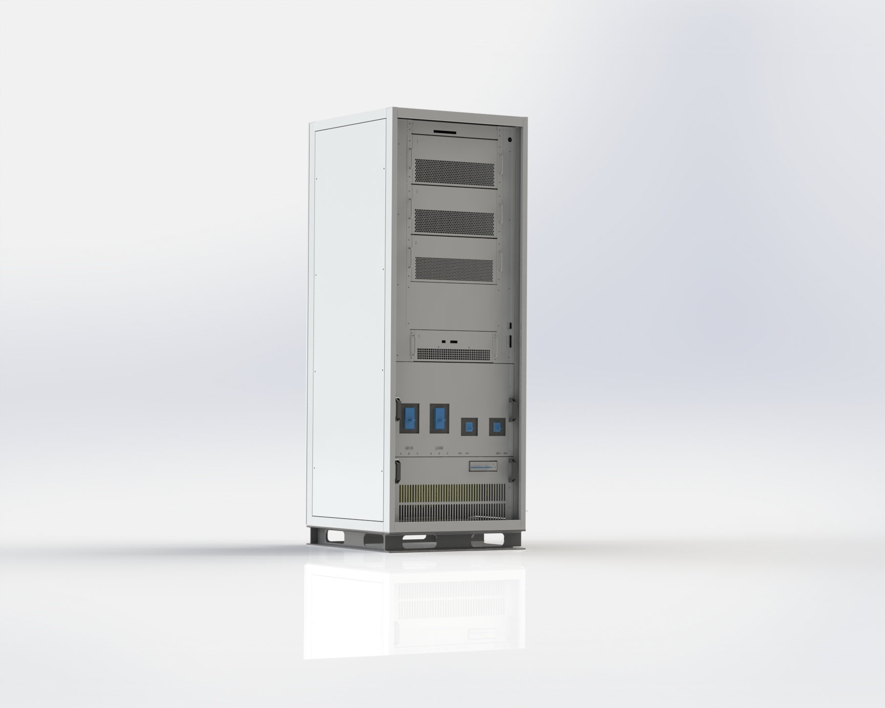
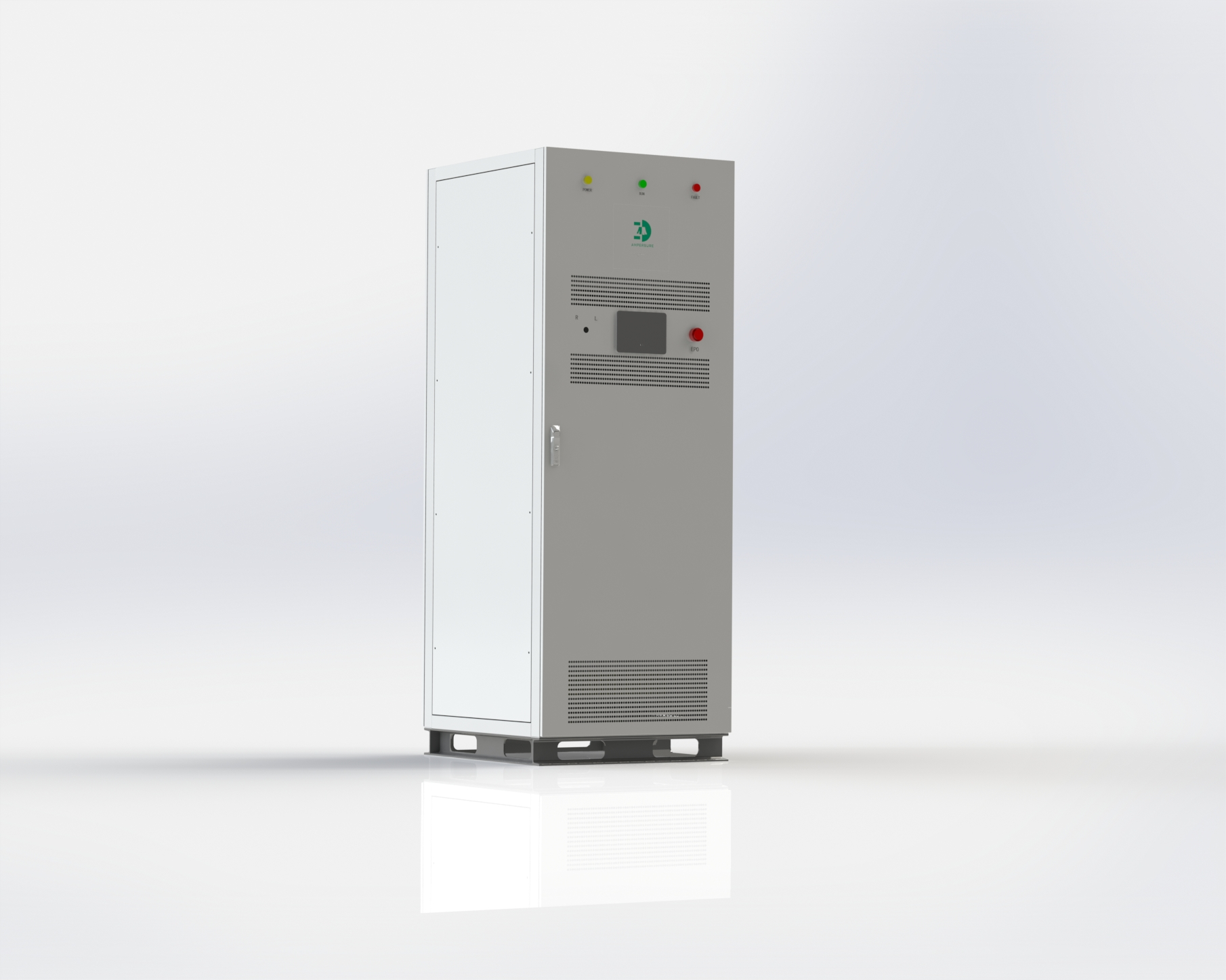
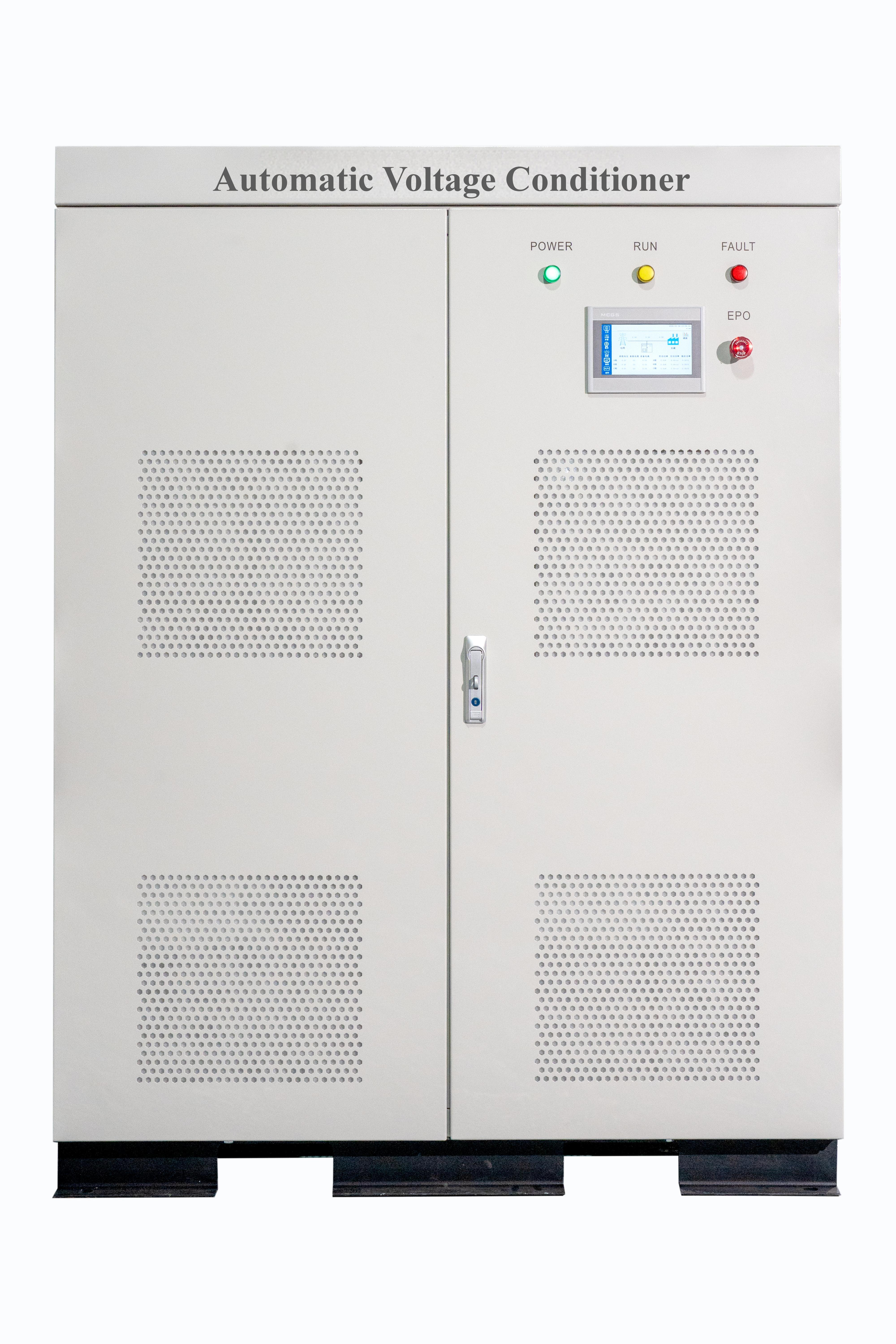
6、AVC Product Appearance
|
Cabinet Modle |
||||
|
Model |
Compensation Capacity (kVA) |
System Voltage(V) |
Dimensions: Width * Depth * Height (mm) |
Cooling |
|
AVC-0.4-30k |
30 |
380 |
800*600*1200 |
Forced Air Cooling |
|
AVC-0.4-45k |
45 |
380 |
800*600*1200 |
Forced Air Cooling |
|
AVC-0.4-60k |
60 |
380 |
800*600*1200 |
Forced Air Cooling |
|
AVC-0.4-80k |
80 |
380 |
800*600*1500 |
Forced Air Cooling |
|
AVC-0.4-100k |
100 |
380 |
800*800*1500 |
Forced Air Cooling |
|
AVC-0.4-150k |
150 |
380 |
800*800*1500 |
Forced Air Cooling |
|
AVC-0.4-300k |
300 |
380 |
800*1000*2100 |
Forced Air Cooling |
|
AVC-0.4-400k |
400 |
380 |
1000*1000*2100 |
Forced Air Cooling |
|
AVC-0.4-500k |
500 |
380 |
1200*1000*2100 |
Forced Air Cooling |
Note: Other specifications are available upon request for customization.